Light Painting with the Raspberry Pi
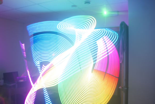
I recently came across some images from Flickr user TxPilot, who has created a light painting wand controlled by an Arduino and has used it to create some stunning photos such as the one below.

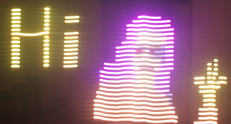
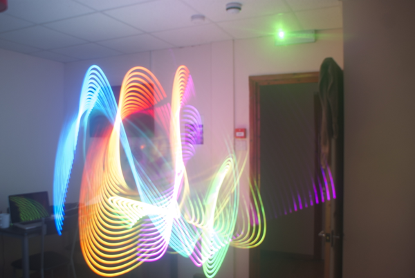
This seemed like a brilliant idea, so I set about making my own. I used a Raspberry Pi rather than an Arduino as prototyping was faster and easier, and it allows me to do a bunch of things that the Arduino would not. The basic idea is that you provide an image file and the light stick will show that image file column by column. If you mount your camera on a tripod and hold the shutter open while moving the light stick along, it reproduces the image in a light trail. The images below show an example input file, and the kind of thing you can produce with it:
Source image:

Results:
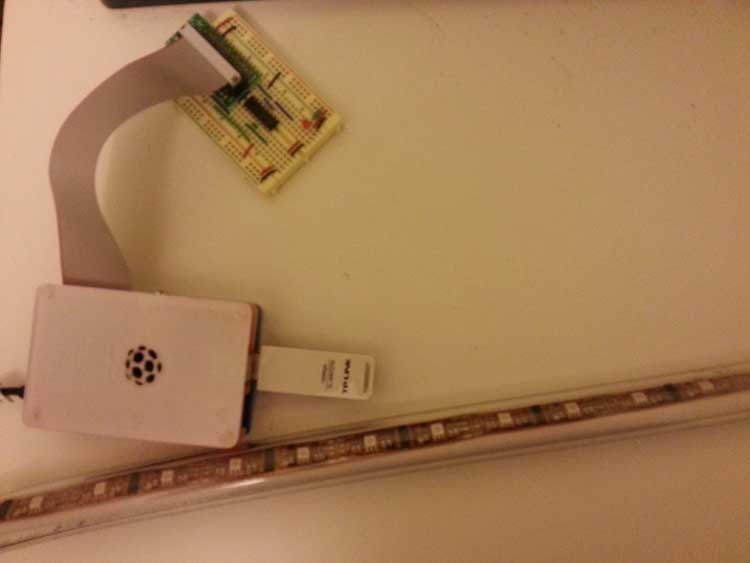
The Pi is using a cheap USB wifi dongle and runs a DHCP a server. When it boots, it sets up an ad-hoc wireless network and boots a small Python web application that provides a control interface to the light wand. This allows anybody with a computer or smartphone to connect to the network, upload an image to the Pi, and control the playback of that image on the light stick. The whole thing runs from a portable battery that’s designed for charging your devices while you’re away from a plug for a long time.
#Technical Information

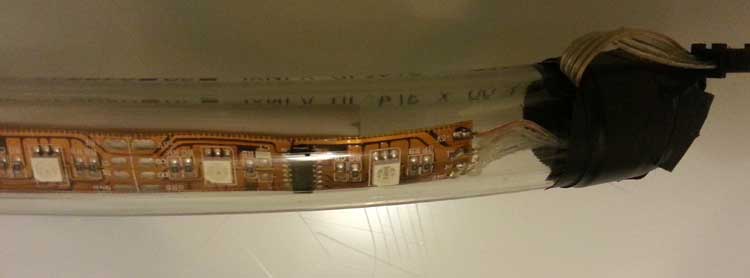
The Raspberry Pi runs a small Python application written using the web.py framework. It uses Twitter Bootstrap for style, layout, and responsive design, and the RPi.GPIO Python module for communicating with the lights. The source code for the Python application can be found here. The lights themselves consist of a flexible strip of 32 individually addressable RGB LEDs.
The Pi communicates using the GPIO pins via SPI to the LED strip, but the RPi outputs 3.3v on these pins. I didn’t have any transistors to hand so I used couple of NOT gates in a 7404 hex inverter chip to bump the logic level to 5v. I don’t need to read from the strip, the 3.3v is higher than the switching voltage for the hex inverter, and the GPIO frequency is pretty low so the 7404 was fine for the job.
You can see an image of the web interface on the right. It is very simple, and consists of a few buttons that control the state of the application (these are shown and hidden at the appropriate times to stop you pressing the wrong thing), a file upload form and a gallery of existing uploaded images. Clicking an image in the gallery will start playing it.
#Parts List and Cost Breakdown
The list of parts can be found below (shipping not included):
- Raspberry Pi - £26.78
- Cute RPi case - £12.95 (optional!)
- TP-Link Wireless USB Dongle - £9.87
- USB Battery Charger Power Supply - £23.99.
- Weatherproof Digital RGB LED strip - £19
I also spent about £6 at a local DIY store for a 1m section of 3/4” clear PVC pipe and 1m of stiff plastic pipe thing that stops it from bending. I used these to construct a clear backbone+shell for the flexible light strip that is entirely waterproof. Total cost comes to about £100 incl. postage. Add a little more if you need prototyping boards and components. The Raspberry Pi GPIO breakout kit is a good choice for connecting the Pi to a breadboard.
Note: The Anker USB power supply is a good choice because it has both a 1A and a 2A output, both rated at 5v. They market this because it can charge your devices faster, but at ~20 mA per LED for a 1m 32-LED strip + ~500mA for the RPi + the wifi dongle, the 2A connection is necessary for this build.