Controlling a Sony Alpha SLR remote release with a microprocessor
I wanted to control my old Sony Alpha SLR with an Atmel AVR. It turns out it’s very easy to do.
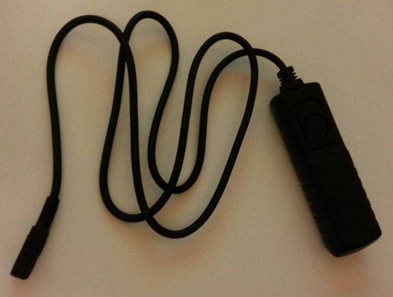
I repurposed a cheap Alpha remote trigger cable from amazon.co.uk (about £3) for this, but you can also make your own connector. See this instructable by Brad Justinen that shows how to mimic the Alpha remote release connector using a 4 pin internal CD-ROM drive audio connector.
Other parts required:
- An optoisolator or relay (relays are more difficult to use)
- 3 single line header pins
- Some solderboard
- A soldering iron and solder
- A drill
- A cable tie or some glue
- A saw
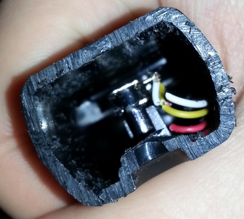
Step 1: Remove the casing around the trigger button
I used a junior hacksaw to chop off the bottom end completely. After doing this you should see three wires. The mechanism simply connects two of them together to focus and then the third to take the photo.
Once the bottom is off, you should be able to use some side cutters to chop off the three wires or de-solder them.
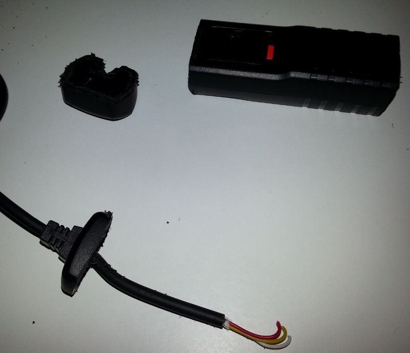
Step 2: Remove the casing around the cable
I used the junior hacksaw again to chop carefully around the end with the cable. The aim is to keep the rubber cable tensioner as part of the cable, not to chop the cable off.
After doing that, you should have something that looks like this:
Step 3: Make the breakout board
I drilled a hole in the solderboard big enough to fit the camera cable, then two smaller holes either side. I fed the cable through and used a cable tie to hold it in place. This allows there to be some tension and tugging without the solder connection breaking. I then soldered each of the three cables into the board and a single row of three headers to connect to a breadboard for prototyping.
Step 4: Wire up the optoisolator
Using an optoisolator means that you can’t accidentally send any current through the camera’s remote release trigger port. It’s likely to be protected but there’s still the chance that it could be damaged if this happened.
The single optoisolator DIL package has four pins. I connected the input side from one of the AVR’s digital out pins to ground, and to the output side I attached the white and yellow cables (focus) to one pin, and the red cable (shutter) to the other. Simply by putting this pin to the HIGH state in the microprocessor I can take a photo with the SLR. Note that you may need a resistor here depending on the optoisolator and the amount of current your chip can drive.
My use case is for time-lapse photography, which is why I wired the two focus pins together. I will set my camera up manually, set to manual focus, then connect the cable. As the camera is in manual focus mode, having the two focus pins connected does nothing.